
Top-Class Test System
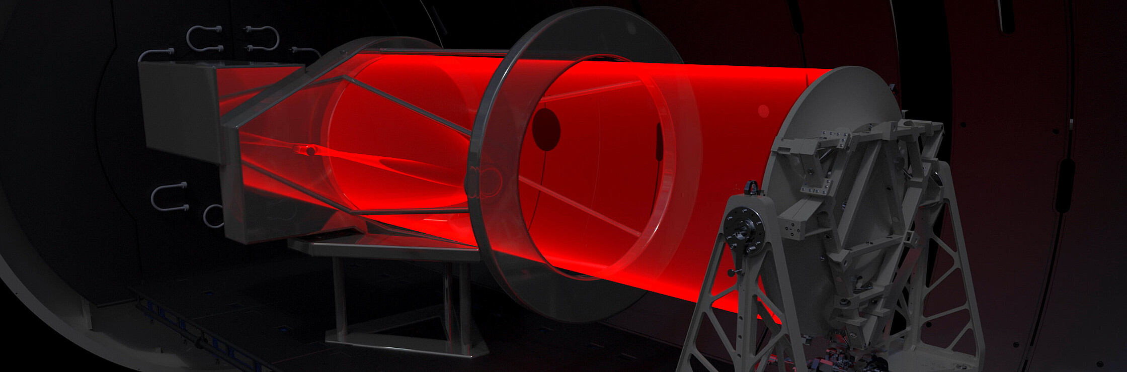
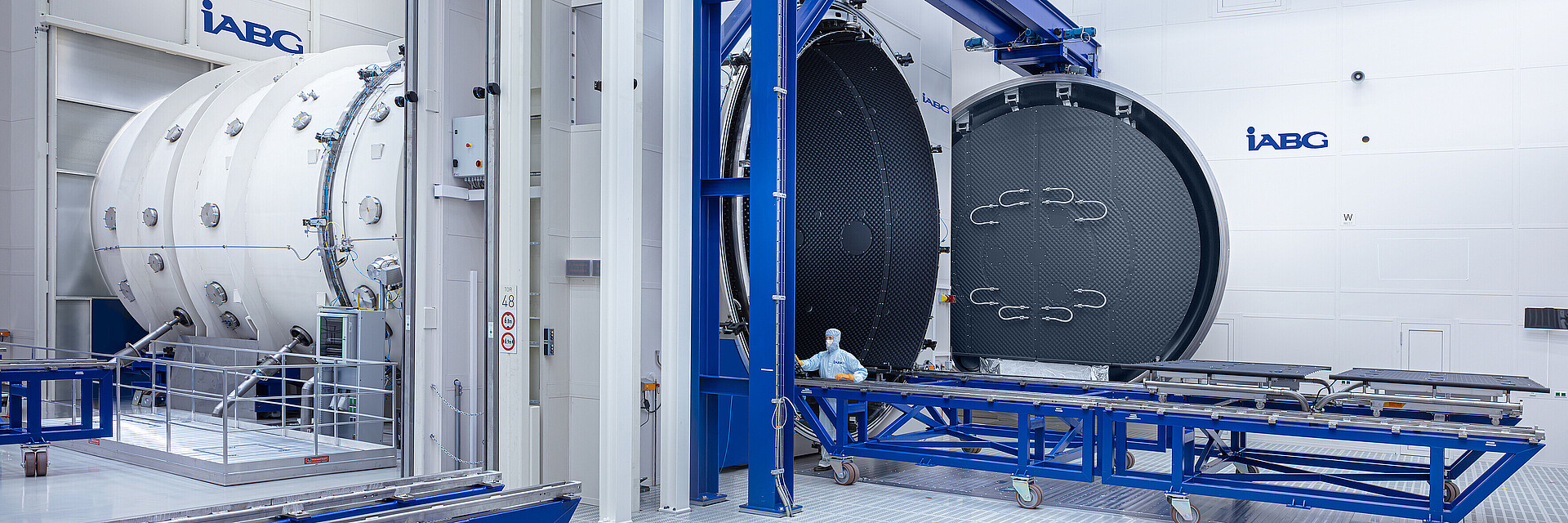
Space-based Earth observation and reconnaissance systems with optical payloads must meet the highest standards. Consequently, test facilities with advanced technical capabilities for qualification, calibration and functional testing of electro-optical systems and components are essential.
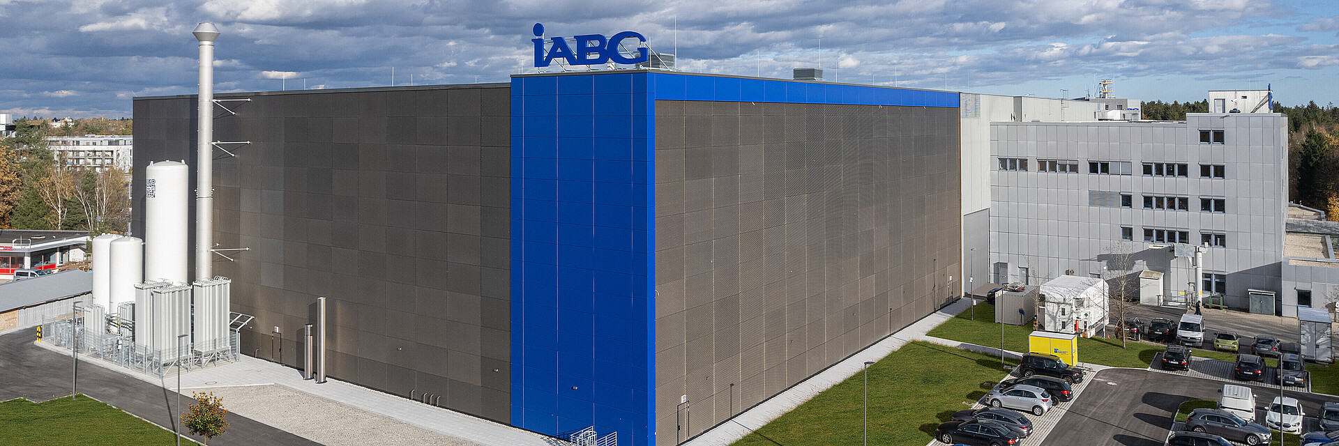
The new Competence Centre Optics (CCO) addresses this need and is the latest addition to our Space Centre.
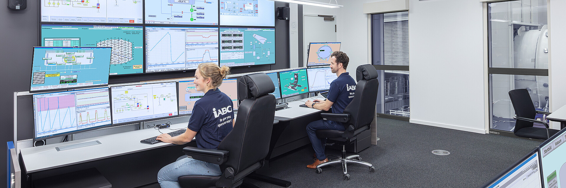
Alongside providing and operating the CCO, we offer expertise in the calibration and verification of optical payload systems. Our team of optical specialists also assists customers with general inquiries regarding optical measurements and test setup design.